An explanation of the differences among the three types of wiring: parallel, switch, and series
An electrical circuit is a closed course through which electricity continuously flows from a source through a hot wire to the device to be powered and then back to the source again through a neutral wire. Along the circuit there may be fixtures, receptacles, and/or switches (protected by housing boxes) connected by either parallel or series wiring.
Wiring may be routed in any of several different ways. For example, the cable for a switch may run through a switch box and then on to the light, or it may run through the light to the switch box via a “switch loop.” Other wires may run through either the switch box or the housing box or both, unswitched, on their way to powering different devices down the line.
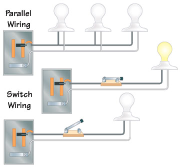
Parallel Wiring
The wiring for most homes is parallel, meaning several devices are powered on a single circuit. Both the hot and neutral wires run through the various housing boxes along the route and branch off to individual fixtures and receptacles.
Switch Wiring
Switches, which are installed on hot wires, allow or disallow the flow of current to a light or other device. A knife-blade switch (shown at right) illustrates the position of the switch when it completes a circuit, allowing electricity to power a device. The illustration below it shows the position of the switch when it interrupts the flow of current from the hot bus bar, disallowing the flow of electricity.

Series Wiring
This type of wiring is rarely used because it operates the same as old-style Christmas lights—when one light burned out, none would illuminate. Series wiring routes the hot wire through several devices and then joins the neutral wire, which leads back to the source.




 Don Vandervort writes or edits every article at HomeTips. Don has:
