A guide to how your home receives and distributes electrical current to lights, receptacles, and appliances.
Have you ever wondered how electricity is delivered to—and routed through—your house? Understanding how a home’s electrical system works can go a long way toward allowing you to easily and safely handle electrical problems when they arise.
The following information will walk you through how a home’s electrical system works.
Your Home Electrical Service
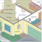
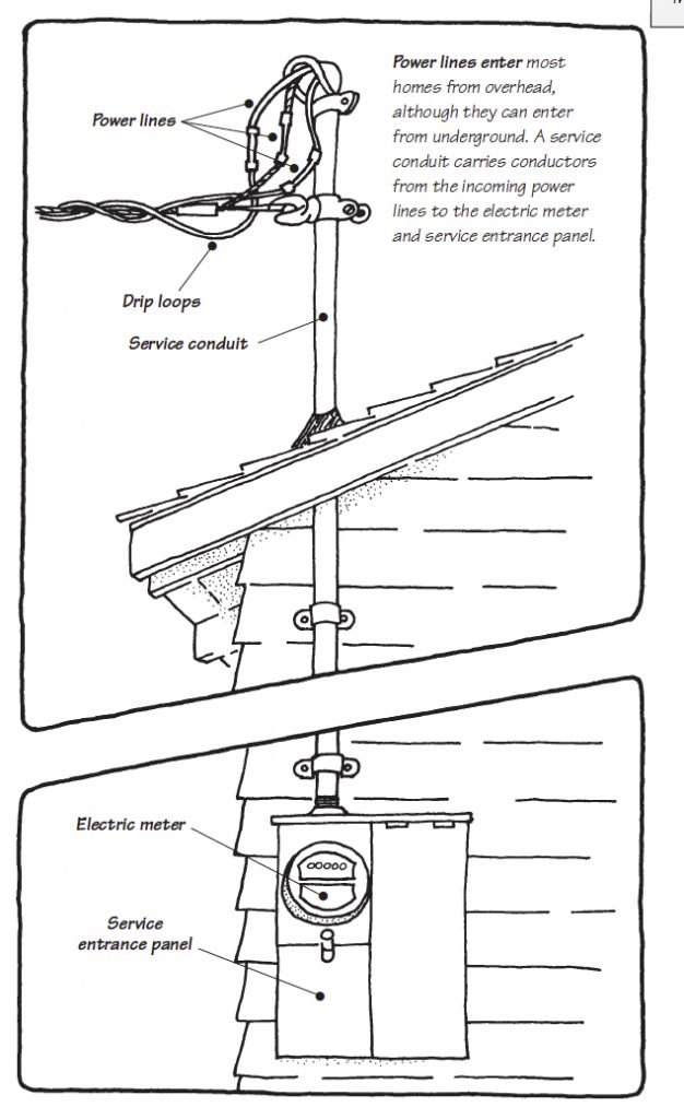
Your home’s electrical system begins with your electric utility company, which sends electrical power to your home through electrical lines overhead from a power pole or underground through buried pipes called “conduit.”
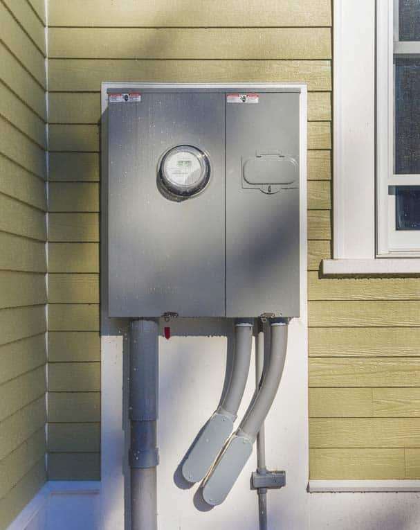
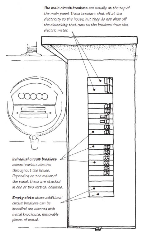
At the point where the power enters your house, you’ll usually find an electric meter and main service panel, as shown in the illustration above and photo below.
Here we look at the load centers—the distribution center or main panel and smaller subpanels used to hook up and control the various electrical circuits.
Main Electrical Panel
Main panels come in scores of sizes and configurations. A panel might be mounted on the outside of the house, either separate from or combined with the electric meter, or on an inside wall, behind the meter.
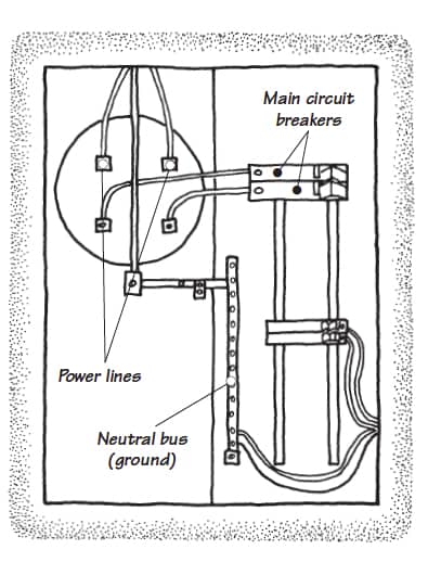
A contemporary main panel receives three incoming electrical service wires and routes smaller cables and wires to subpanels and circuits throughout the house.
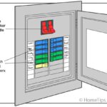
Power lines connect to the two top lugs of the meter mount. The main circuit breakers pull electricity from the two bottom lugs when the meter is in place to complete the circuit. The main breakers deliver electricity to the two bus bars, which in turn pass it along to the secondary circuit breakers.
For safety, all circuits should be grounded: A continuous conductor (often solid copper) should run from the neutral connector inside the panel to a ground such as a water pipe or metal rod driven directly into the ground. Unlike the hot bus bars, a neutral bus bar does not have an over-current protection device so it can maintain 0 volts at all times.
Circuit Breakers and Fuses
The main panel also includes some type of mechanical device for disconnecting the house’s electrical circuits from the incoming power. In most contemporary systems, this device is a circuit breaker or simply “breaker.” A circuit breaker is a switch that may be shut off manually or be tripped automatically by a failure in the electrical system—usually an overload that could cause the wires to heat up or even catch fire.
Other types of disconnects utilize levers and fuses—you pull down on a lever or pull out a fuse block to shut off the power to the house’s circuits.
The maximum amperage that a service panel may deliver at one time is marked on the main breaker. For most homes, a 100-amp main is sufficient to handle all electrical needs; however, many new-home builders now install 150-amp or 200-amp services to ensure plenty of capacity. Electrical service panels rated at 60 amps or lower are undersized for contemporary needs.
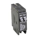
Every circuit breaker is rated for the type of wire and load required by its circuit. The most typical capacities for lighting and receptacle circuits are 20-amp and 15-amp. Standard breakers for 120-volt circuits take one slot.
Breakers for 240-volt circuits take two slots. Though the typical 220 breaker is twice as fat as a standard breaker, some manufacturers make extra-thin breakers that take only half the space of standard breakers. Large-capacity circuit breakers are used for electric appliances such as ovens, water heaters, clothes dryers, and air conditioners, which draw a lot of power.
Subpanels and Branch Circuits
Larger circuit breakers may also connect to secondary panels, called subpanels. Subpanels have their own set of circuit breakers and power specific appliances or areas of the house. A subpanels is often located in a different part of the house. You might, for example, find one near your home’s air conditioner.
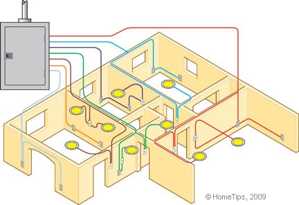
The circuits that deliver electricity to the various areas of a home are referred to as branch circuits. Branch circuits originate at a service distribution panel—either a main panel or a subpanel.
For a deeper dive into electrical panels, see Electrical Service Panels and Circuit Breakers: How They Do Their Job.
For information on wiring, see Home Electrical Wiring.
Outdoor Circuits
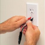
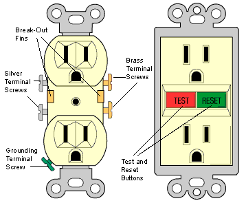
Outdoor, kitchen, and bathroom electrical receptacles should be protected by a special ground-fault circuit interrupter (GFCI) circuit breaker to guard against electrocution. Because it is highly sensitive to any short, this type of breaker may need resetting more frequently than standard breakers and should be tested periodically.
If a home electrical circuit it supplying power to just a few outdoor receptacles, you can protect those receptacles by installing special GFCI receptacles. For more about GFCI receptacles, see Electrical Receptacle Buying Guide.




 Don Vandervort writes or edits every article at HomeTips. Don has:
